Channel steel is classified as a "Bar Size Shape" when its greatest dimension (excluding length) is less than 3 inches.Above is a general properties guide that can be considered representative of HR structural shapes conforming to ASTM A36.ASTM A36 is generally not heat treated but is typically stress relieved prior to grinding or machining or after welding and prior to machining. In the designation of MC American channels, a letter or letters precedes the size and weight per foot, ie: C3 x 4.1# is the AISI designation for a channel 3" wide at its base and 4.1 pounds weight per foot standard structural channel.
It is a "Structural Shape") when at lease one of its dimension (excluding length) is 3 inches or greater. Used for general structural purposes, for use in riveted, bolted, or welded construction of buildings, bridges, machinery, etc. Stress Relieve 1100°-1250°F. Typical Stress relieve soak time - one hour per inch of thickness. MC American steel channel may be equal or unequal dimension (ie: 2 x 2 x 1/4" hr angle / 3 x 2 x 1/4" hr angle). "MC" shapes are channels that cannot be classified as "C" shapes.
HR angle is measured by its legs dimension on the exterior and by its thickness.These shapes conform to ASTM A36 in its manufacture and mechanical tolerances. Used for booms, rails, braces, frames, brackets, cross-members, liners, truck trailers, truck beds, racks, etc.ASTM A36 is easily welded by all welding processes and the welds and joints produced are of extremely high quality. Subject to a deduction from the above percentage of elongation for thicknesses under 5/16" and over 3/4".The essential part of these MC American steel channels is that the inside flange surfaces of American Standard channels have approximately a 16-2/3% slope.
Dimensions:
ASTM A 6/A 6M - 07
Tolerances:
ASTM A 6/A 6M - 07
Surface condition:
According to ASTM A 6/A 6M - 07
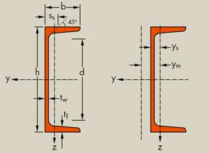
| Designation | Depth | Width | Thick ness Web |
Thick ness Flange |
Sectional Area |
Weight | Section of Modulus - Wx |
Section of Modulus - Wy |
| in | in | in | in | in**2 | lb/ft | in**3 | in**3 | |
| MC 18 x 58 | 18.00 | 4.200 | 0.700 | 0.625 | 17.1 | 58 | ||
| MC 18 x 51.9 | 18.00 | 4.100 | 0.600 | 0.625 | 15.3 | 51.9 | ||
| MC 18 x 45.8 | 18.00 | 4.000 | 0.500 | 0.625 | 13.5 | 45.8 | ||
| MC 18 x 42.7 | 18.00 | 3.950 | 0.450 | 0.625 | 12.6 | 42.7 | ||
| MC 13 x 50 | 13.00 | 4.412 | 0.787 | 0.610 | 14.7 | 50 | ||
| MC 13 x 40 | 13.00 | 4.185 | 0.560 | 0.610 | 11.8 | 40 | ||
| MC 13 x 35 | 13.00 | 4.072 | 0.447 | 0.610 | 10.3 | 35 | ||
| MC 13 x 31.8 | 13.00 | 4.000 | 0.375 | 0.610 | 9.35 | 31.8 | ||
| MC 12 x 50 | 12.00 | 4.135 | 0.835 | 0.700 | 14.7 | 50 | ||
| MC 12 x 45 | 12.00 | 4.010 | 0.710 | 0.700 | 13.2 | 45 | ||
| MC 12 x 40 | 12.00 | 3.890 | 0.590 | 0.700 | 11.8 | 40 | ||
| MC 12 x 35 | 12.00 | 3.765 | 0.465 | 0.700 | 10.3 | 35 | ||
| MC 12 x 31 | 12.00 | 3.670 | 0.370 | 0.700 | 9.12 | 31 | ||
| MC 12 x 14.3 | 12.00 | 2.125 | 0.250 | 0.313 | 4.19 | 14.3 | ||
| MC 12 x 10.6 | 12.00 | 1.500 | 0.190 | 0.309 | 3.10 | 10.6 | ||
| MC 10 x 41.1 | 10.00 | 4.321 | 0.796 | 0.575 | 12.1 | 41.1 | ||
| MC 10 x 33.6 | 10.00 | 4.100 | 0.575 | 0.575 | 9.87 | 33.6 | ||
| MC 10 x 28.5 | 10.00 | 3.950 | 0.425 | 0.575 | 8.37 | 28.5 | ||
| MC 10 x 25 | 10.00 | 3.405 | 0.380 | 0.575 | 7.35 | 25 | ||
| MC 10 x 22 | 10.00 | 3.315 | 0.290 | 0.575 | 6.45 | 22 | ||
| MC 10 x 8.4 | 10.00 | 1.500 | 0.170 | 0.280 | 2.46 | 8.4 | ||
| MC 10 x 6.5 | 10.00 | 1.17 | 0.152 | 0.202 | 1.91 | 6.5 | ||
| MC 9 x 25.4 | 9.00 | 3.500 | 0.450 | 0.550 | 7.47 | 25.4 | ||
| MC 9 x 23.9 | 9.00 | 3.450 | 0.400 | 0.550 | 7.02 | 23.9 | ||
| MC 8 x 22.8 | 8.00 | 3.502 | 0.427 | 0.525 | 6.70 | 22.8 | ||
| MC 8 x 21.4 | 8.00 | 3.450 | 0.375 | 0.525 | 6.28 | 21.4 | ||
| MC 8 x 20 | 8.00 | 3.025 | 0.400 | 0.500 | 5.88 | 20 | ||
| MC 8 x 18.7 | 8.00 | 2.978 | 0.353 | 0.500 | 5.50 | 18.7 | ||
| MC 8 x 8.5 | 8.00 | 1.874 | 0.179 | 0.311 | 2.50 | 8.5 | ||
| MC 7 x 22.7 | 7.00 | 3.603 | 0.503 | 0.500 | 6.67 | 22.7 | ||
| MC 7 x 19.1 | 7.00 | 3.452 | 0.352 | 0.500 | 5.61 | 19.1 | ||
| MC 6 x 18 | 6.00 | 3.504 | 0.379 | 0.475 | 5.29 | 18 | ||
| MC 6 x 15.3 | 6.00 | 3.500 | 0.340 | 0.385 | 4.50 | 15.3 | ||
| MC 6 x 16.3 | 6.00 | 3.000 | 0.375 | 0.475 | 4.79 | 16.3 | ||
| MC 6 x 15.1 | 6.00 | 2.941 | 0.316 | 0.475 | 4.44 | 15.1 | ||
| MC 6 x 12 | 6.00 | 2.497 | 0.310 | 0.375 | 3.53 | 12 | ||
| MC4 x 13.8 | 4.00 | 2.5 | 0.5 | 13.8 | ||||
| MC3 x 7.1 | 3.00 | 1.938 | 0.312 | 7.1 |