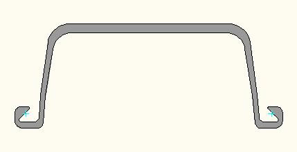
The design of Type II sheet pile was performed in accordance with the requirements of BS5950-1. The zone of optimal anchor location is shown in Fig.11. A comprehensive range of junction piles can be formed by welding a C9 hot rolled section onto the main sheet pile at the appropriate location and angle. The effective penetration level, or the maximum depth where active pressure exists, is first determined.
The specified coating for SP-II steel sheet piles is for shot blasting to SA2.5 followed by 2 layers of 250 micron Jotamastic 87. This level is taken as the level of maximum moment beneath the dredge line. The diagram below illustrates the comprehensive range of hot rolled special sections that is available for use. Please note that generally bent corners will be supplied as single piles.
Beyond this level counter resistance begins to manifest. If there is no maximum moment level the effective penetration is taken as taken to be the end of type 2 sheet piling. Corrosion was considered for a period of 35 years. The Piles had the full 22m length both sides with paint applied. Capacity of the waling beam was designed to maintain a factor of safety of 1.2 in static conditions and 1.1 in seismic conditions. Type NS-SP, SKSP, TSP, FSP,GSP, ISP, JSP, KSP, NKSP JFE, JFESP are all 400x100x10.5.
The special section is attached to the main sheet pile by welding in accordance with EN12063 and is set back from the top of the pile by 200mm to facilitate driving. The SP-2 sheet piles must be situated in the passive wedge zone as shown to fully ultilize the earth resistance.
The coating was applied to the top 22.3m of the front of the tubular Piles and the back 4m.

| Section | Dimensions | Sectional Area | Mass | Moment of inertia | Modulus of section | |||
| Width | Height | Thickness | Pile | Wall | ||||
| b | h/2 | t | ||||||
| mm | Mm | mm | cm2/pile | kg/m | kg/m2 | cm4/m | cm3/m | |
| Ⅱ | 400 | 100 | 10.5 | 61.2 | 48 | 120 | 8740 | 874 |

